
MAKING OF PHOTO vs RENDER
Below are some of the techniques I used in my Photo vs Render study


3d Modeling:
Every element must be an exact reproduction so it would match the photography. So combined with the reference images I made measurement notes. Starting with the Kitchen appliances. Many manufacturers offer free 3D files of their products directly on their website. 3D Warehouse is another good site for quick free models. Free models often need refinement and detail, but it’s a good starting point.


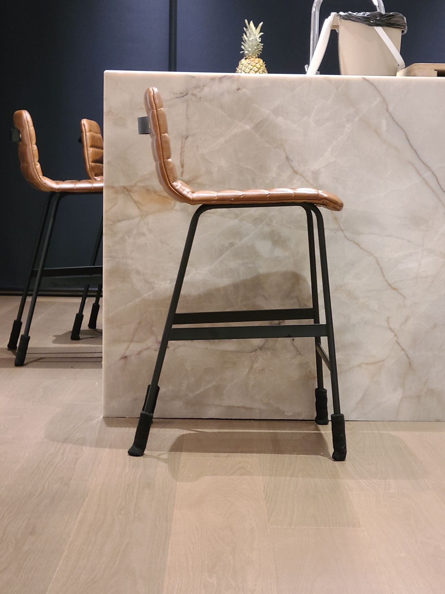
STOOL MODEL
To create the stool, I imaged it as a flat object that was bent to form the back and seat. Starting with simple polygons, I crudely shaped folds, and added thickness, knowing it will be smoothed with a turbosmooth modifier. The modifier deforms the object thereby creating the final shape. Stitches are created from an generated spline of the final mesh and use the MCG Stitches script.

TABLE
I took a series of photos of the live edge table with the plan make a mesh using photogrammetry, but I couldn’t get a generate a usable mesh. Instead, I photo merged the separate surfaces in photoshop and mapped it onto an extruded spline of the table. An easy way to generate splines that perfectly match an 2D image is to outline the image with a marque in Photoshop, right click and select “make work path” then “file > export > paths to illustrator”. Then import that .AI object into 3ds max, extrude and apply a UVW map to the bounding box. You now have a perfect cut out of your 2D shape.
To generate a clean mesh and a single texture, I copied the extruded spline, added a subdivider modifier, and the retopology modifier (which was introduced in version 2021). This mesh will be texture baked from the extruded mesh, so I add a push modifier to make it slightly larger than the extruded mesh. (image)
Now that I have a clean mesh and a single diffuse texture, I generate noise and reflection maps in Photoshop. To add extra detail in very bumpy areas of the table, I tessellated those selected polygons and applied a displacement modifier which has a bump map generated from the diffuse.
Texture & Materials:
For the floors I used Substance Player and Poliigon’s Wood Floor Generator smart material. I was surprised how well it matched considering its procedurally generated. In photoshop I added some dust and dirt to the reflection layers, but it doesn’t show up in the rendering.

The quartzite countertop is a photo of the slab before it was installed, with highlights and shadows photoshopped out, but it is not tilable. I don’t have a camera other than the one on my phone, so its denoised and enlarged using Topax Gigapixel. Real quartzite is translucent, and while I would love to include that look in the renderings, it just wasn’t necessary. It does have a “clear coat” blend to provide that extra high polish gloss similar to a car paint shader.

The stainless-steel material was the most challenging for me. I just could not get a single material to work across all objects and lighting conditions! I could never settle on the right IOR and anisotropy amount. Which is 11 and 0.65 respectively. You need to place a gradient map in the anisotropy direction as below. Adjust the rotation to get the highlight look that matches your object.

Lighting:
The majority of the interior is illuminated completely from a free HDRI map I found on NoEmotion.net. Because I was trying to match real life photos, I found it necessary to recreate the entire exterior as it was the day of shooting and use an HDRI that also matched those conditions. Without an accurate exterior model, the global illumination never quite matched.
Interior photography often uses a soft indirect flash to balance the image, so I recreate this with a soft disk light pointing away and behind the camera.
In addition to the flash, there are Fstorm light portals outside all the glazing, and in the case of the large rear patio doors I found single wide extruded arc produced more accurate results than the typical plane that is coplanar with the glazing.
Since the final photographs are actually HDR images themselves, and composited from a combination of various light configurations, I discovered an additional light source was needed. Each window has a self illuminated material that has be carefully tuned to provide the minimal about of white light.

Cloth and Tyflow
The cloth has been simulated with Tyflow, the fine cloth details use a mesh I created to match the towels. It’s a repeating pattern that is scatter using Fstorm Geopattern. I love Geopattern, its texture mapping, but in 3D.
The skull towel was simulated with a simplified proxy plane, the skull towel would break when simulated because it contained irregular triangles, so its referenced using the Skin Wrap modifier directly to the Tyflow object.

Rendering and Post Production
Fstorm render settings are very simple. Each camera there is nothing more to adjust than the tone mapping, glare and camera settings. The environment multiplier remains at 1.0 throughout all cameras, and the kernel exposure is set to 200 for the brighter areas, and 250 for dimmer areas. The camera exposure ranges from 400 to 1500 with gamma set to 1.0

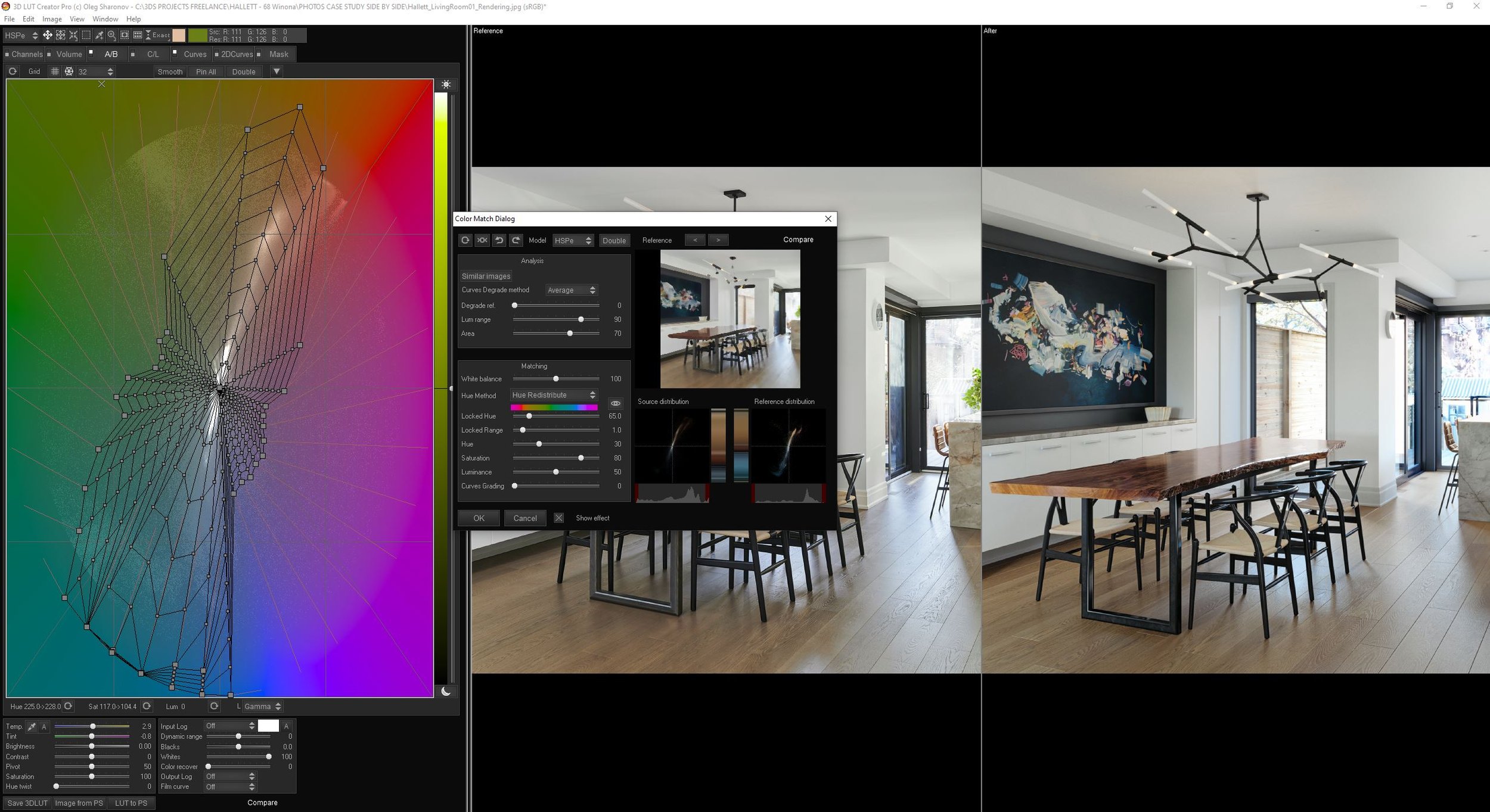
Using a 32 bit draft render, I created a custom LUT using 3D LUT Creator to bring the saturations and hues more inline with the photographs. There is a powerful “color match to reference” feature, along with a tonne of other grading tools not found in Photoshop.
I used the exported LUT from the color match in the enabled LUT slot under Tone Mapping in the Fstorm render settings. The average strength setting was 0.7 since its also combined with adjustments to the contrast and burn value settings for each camera.
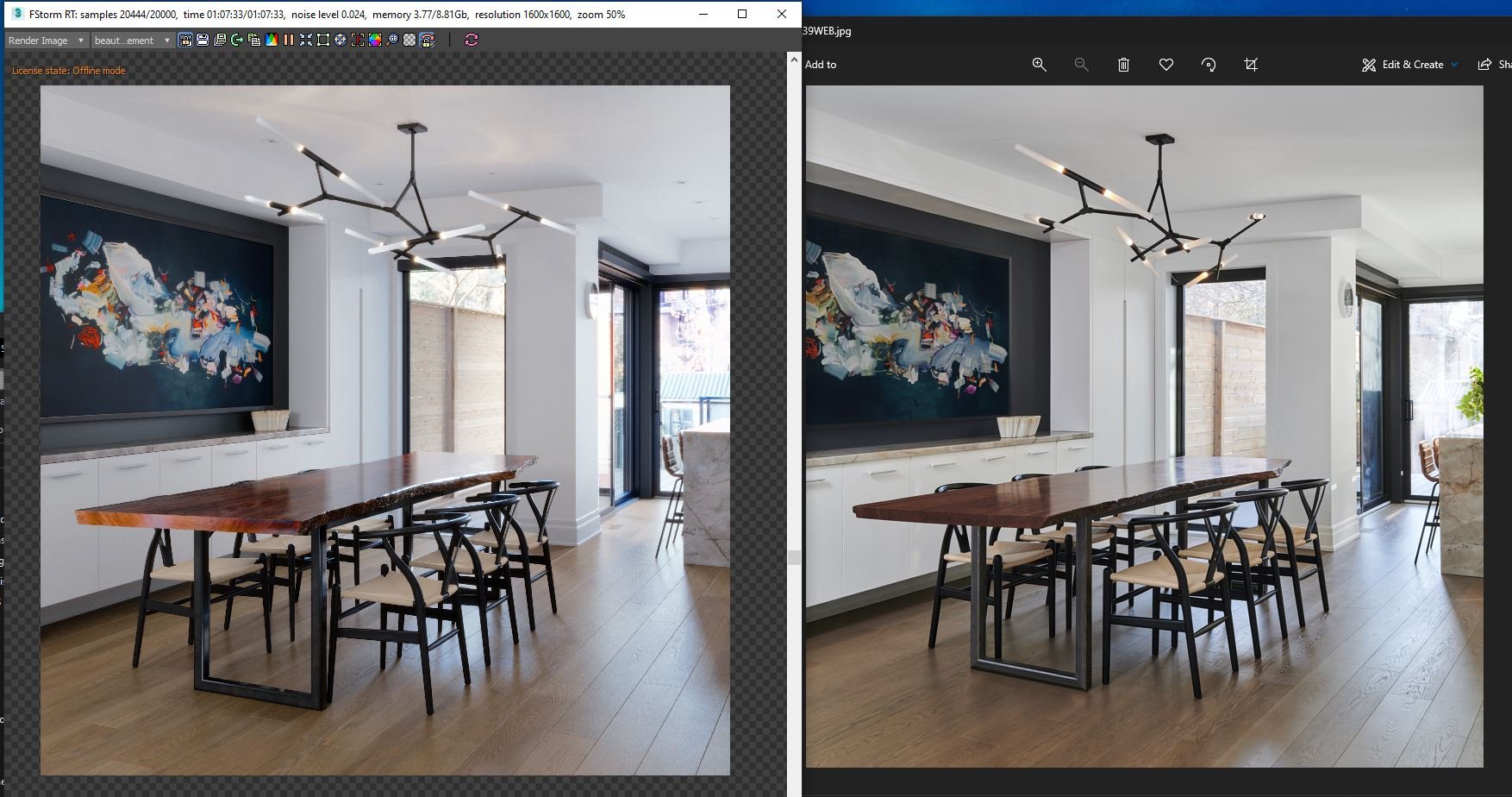
As you can see from the screenshot of the RT render window next to the photograph, at this point there is almost no need for postproduction. Minor level adjustments and the masking of specific objects like the leather of the stool were made in order to more closely match real life. And you may notice that the photographer removed the potlights and outlets in post, where as I kept them in the renderings!

GPU Rendering
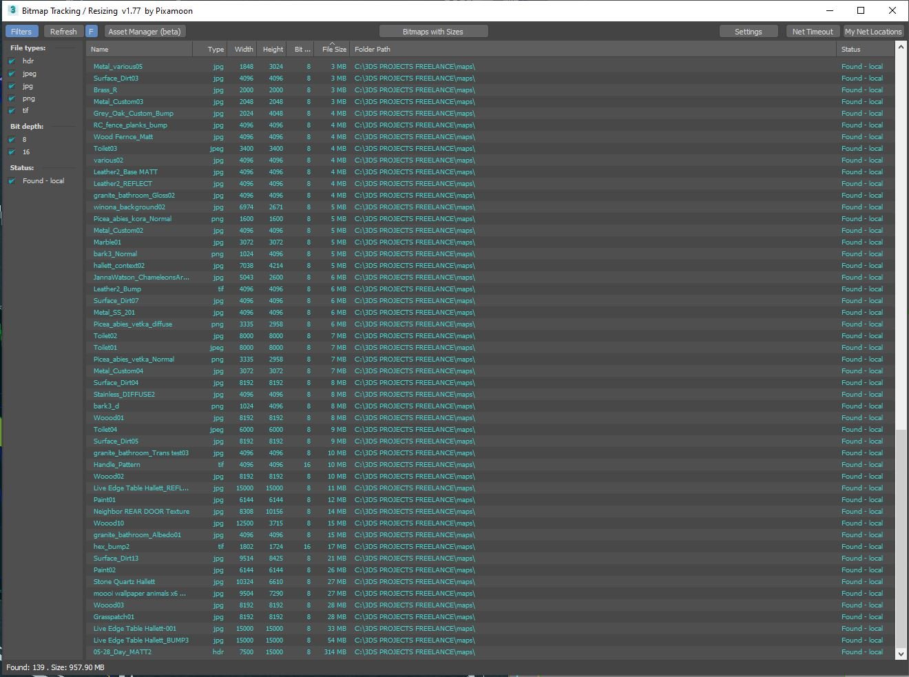
Fstorm is an unbiased GPU render engine. Which means the entire scene has to be contained within the available VRAM of the graphic engine. Proxies only reduce the 3ds max saved file, the polycount of those proxies will still be added to the GPU resources. The only way to fit your scene into your graphic cards VRAM is to 1) reduce poly count 2) use instances as much as possible 3) reduce bitmap texture size. To help with bitmap size management I rely heavily on Pixamoon’s script which makes the entire process easy. If you run out of VRAM simply reduce or convert to JPG, add a suffix such as _2K and save to the same directory. You can always load the high resolution image if you ever notice you’ve degraded the bitmap to small. Fstorm also has a built compression, which works ontop of your compress bitmaps. For diffuse and reflection maps, heavy JPG compression rarely makes a noticeable difference. Fine detailed bump and displacements maps often require the full uncompressed TIFs, which you can always revert back too since the script never over writes the original file.
Final comments:
This was an absolute passion project for me and matching a rendering to real life is something I’ve wanted to create and share since the beginning of my career. There are so many minor adjustments that went into this universal setup that I couldn’t possible cover it all, if you would like to dive deeper into this scene. It is available for purchase on my website. Hallettvisual.com